04 lut Patentowy kalendarz adwentowy 2020
Pomimo wszystkich „niespodzianek” jakie sprezentował nam rok 2020 udało nam się kolejny raz przedstawić patentowy kalendarz adwentowy. Dlatego też chcielibyśmy chociaż na chwilę powrócić do świątecznej atmosfery przez podsumowanie tego projektu. Dla każdego wynalazku zaprezentowaliśmy pełną treść ochrony uzyskanej w wyniku patentu lub wnioskowanej przez zgłaszającego – zastrzeżenia patentowe.
Figurka z tańczącymi reniferami
Numerem jeden na naszej liście była ta urzekająca, świąteczna figurka:
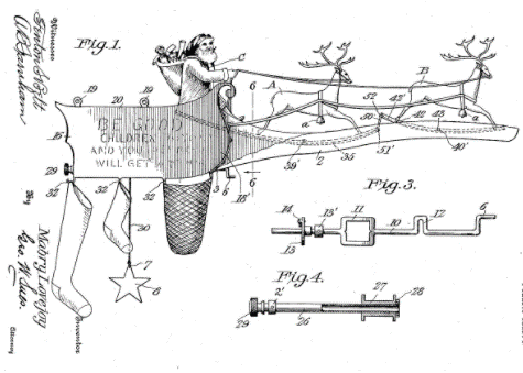
Jednak język zastrzeżeń patentowych bywa już mniej „urzekający” – jest niemalże „brutalny”. Tytuł wynalazku US1068147 to Mechanical Toy, natomiast zastrzeżenie brzmi następująco:
1. In combination, a receptacle, a crank shaft ending in an operating handle carried by said receptacle, a supporting plate extending from one end of said receptacle, a rocker plate pivotally secured to said supporting plate, and a connecting rod extending from said crank to said rocker plate.
Warto dodać, że to jedno z najstarszych znalezisk w tegorocznym zestawieniu – zgłoszenie pochodzi z 1912 roku!
Patent US1068147 – Mechanical Toy
Skarbonka w kształcie Świętego Mikołaja
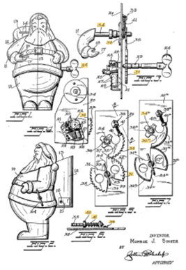
Jak wiadomo najlepsze prezenty to takie, które dajemy … sami sobie. Oczekiwanie na ten wspaniały czas może umilić nam skarbonka w kształcie Świętego Mikołaja. Zgodnie z opisem wynalazku, to urządzenie ma zachęcać do regularnego oszczędzania. W nagrodę za wrzucenie monety Mikołaj „zaśpiewa” nam piosenkę. Co ciekawe, patent został udzielony na taki wynalazek. Czy to nie brzmi jak świąteczny cud?
Zastrzeżenie niezależne:
1. A musical bank comprising a body resembling the figure of a creature and having arms, a plate mounted in said body, top and bottom shafts passing through said plate and extending beyond both sides thereof, one of said arms being mounted on one end of said top shaft for rotation, a segment mounted on the other end of said top shaft having a rubber peripheral edge, means urging said segment gear in a direction to lower said one arm, a yieldable abutment for stopping said segment gear in its movement in said one direction, a music box having a spring associated with the end of said bottom shaft corresponding to said arm end of said top shaft, said bottom shaft being rotatable to wind up said music box spring, a key on the other end of said bottom shaft for turning same to wind said music box spring, said bottom shaft being rotated by said music box spring, a cam wheel on said bottom shaft beneath said segment gear and having two spaced cams, each provided with a rubber peripheral edge for alternately driving said segment, said cani wheel running backward over said segment during winding, said yieldable abutment permitting further backward rotation of said segment to clear said cam wheel during winding, the spaces between said cams permitting return movement of said segment at the end of its engagement with each of said cams.
Patent US2635383 – Santa Claus bank
Urządzenie dozujące prezenty
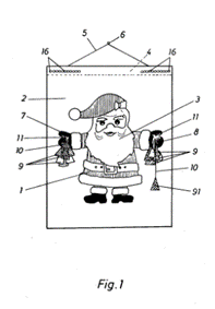
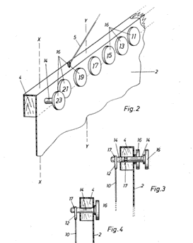
Dzień 3. – mieszkania i domy przyozdobione, budżet prezentowy przygotowany. Czas zająć się konkretami. Jeśli mamy wielu gości do obdarowania, pomocne może okazać się urządzenie dozujące prezenty. Zdecydowanie pozwoli usprawnić rozdawanie prezentów i może być przedstawiane jako Święty Mikołaj (a także Gwiazdor, Aniołek czy Dzieciątko!). Wynalazek został doceniony przez ekspertów USPTO, ponieważ prawo zostało skutecznie udzielone.
Zastrzeżenie niezależne:
1. A gift dispensing device for distributing gifts to children, particularly a replica of a figure which dispenses gifts during the Advent period, comprising:
a. a support upon the front of which a replica of a figure is exhibited with at least one arm;
b. a plurality of containers suspended from each arm;
c. dispensing means disengageable with said support and connected to said containers for lowering said containers.
Patent US4073405 – Gift-dispensing device
Automatyczny system gaśniczy dla choinki świątecznej
Często możemy usłyszeć „bezpieczeństwo przede wszystkim” – wydawałoby się, że ze strony choinki nic nam nie grozi, ale wypadki się zdarzają. Kolejnym patentem, który wyróżnił się nowością i poziomem wynalazczym jest system gaśniczy dla choinki świątecznej.
Co ciekawe, może z powodzeniem służyć jako ozdoba.
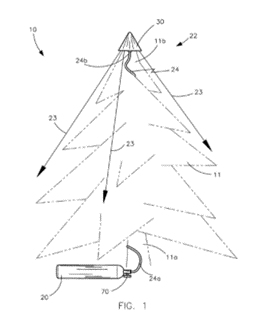
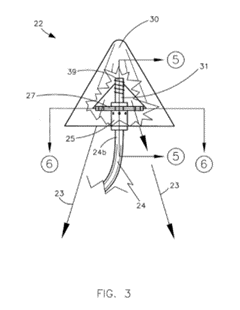
Zastrzeżenia niezależne:
1. A Christmas tree fire prevention device for reducing a likelihood of fire damage to an existing Christmas tree and surrounding objects, said Christmas tree fire prevention device comprising: an air-pressurized reservoir adapted to be removably positioned at a base of the existing Christmas tree; a fire-retardant agent maintained at an initial compressed state by said air-pressurized reservoir; means for automatically discharging said fire-retardant agent along a diverging target path when an unsafe triggering event is detected, said target path beginning at an apex of the existing Christmas tree and terminating at the base of the existing Christmas tree; wherein said unsafe triggering event is detected when a real-time ambient temperature level surrounding the existing Christmas tree elevates beyond a predefined maximum threshold temperature level; wherein said automatic fire-retardant agent discharging means is adapted to be camouflaged and removably attached to the existing Christmas tree; wherein said automatic fire-retardant agent discharging means comprises a flexible hose having opposed lower and upper ends coupled to said reservoir and adapted to be positioned at the apex of the existing Christmas tree respectively; a valve having an axial bore formed therein and being directly connected to said upper end of said hose, said axial bore being in fluid communication with said upper end of said hose; an agitator journaled about said valve and partially seated within said axial bore, said agitator having a plurality of spring-actuated cutting blades situated within said axial bore and further having a plurality of fans radially spaced exterior of said valve; and a guard covering said agitator and said valve respectively; wherein said fire-retardant agent is maintained at a pressurized state within said hose and said axial bore during non-operating conditions, said fire-retardant agent being upwardly urged through said hose and said axial bore when said triggering-event is detected, said fire-retardant agent being subsequently dispersed by said fans while traveling down said target path after reaching an upper limit of said guard.
8. A Christmas tree fire prevention device for reducing a likelihood of fire damage to an existing Christmas tree and surrounding objects, said Christmas tree fire prevention device comprising: an air-pressurized reservoir adapted to be removably positioned at a base of the existing Christmas tree, said air-pressurized reservoir being suitably sized and shaped for simulating a gift-wrapped present; a fire-retardant agent maintained at an initial compressed state by said air-pressurized reservoir; means for automatically discharging said fire-retardant agent along a diverging target path when an unsafe triggering event is detected, said target path beginning at an apex of the existing Christmas tree and terminating at the base of the existing Christmas tree; wherein said unsafe triggering event is detected when a real-time ambient temperature level surrounding the existing Christmas tree elevates beyond a predefined maximum threshold temperature level; wherein said automatic fire-retardant agent discharging means is adapted to be camouflaged and removably attached to the existing Christmas tree; wherein said automatic fire-retardant agent discharging means comprises: a flexible hose having opposed lower and upper ends coupled to said reservoir and adapted to be positioned at the apex of the existing Christmas tree respectively; a valve having an axial bore formed therein and being directly connected to said upper end of said hose, said axial bore being in fluid communication with said upper end of said hose; an agitator journaled about said valve and partially seated within said axial bore, said agitator having a plurality of spring-actuated cutting blades situated within said axial bore and further having a plurality of fans radially spaced exterior of said valve; and a guard covering said agitator and said valve respectively; wherein said fire-retardant agent is maintained at a pressurized state within said hose and said axial bore during non-operating conditions, said fire-retardant agent being upwardly urged through said hose and said axial bore when said triggering-event is detected, said fire-retardant agent being subsequently dispersed by said fans while traveling down said target path after reaching an upper limit of said guard.
Patent US7963343 – Automatic fire extinguishing system for an existing Christmas tree and associated method
„Samoubierająca się” choinka
Nasza propozycja nr 5 to coś dla tych zabieganych i zapracowanych. Stelaż pokryty tkaniną, na którym zawieszone są ozdoby. Można ją rozstawić i ubrać jednym kliknięciem.
Zastrzeżenie:
1. A pop-up Christmas tree comprising: a cone shaped fabric member; a standard motorized telescoping antenna assembly; a hollow base portion; a lid portion; a plurality of horizontally disposed fabric supporting frames; a plurality of vertically disposed frame supporting cords; a plurality of standard exterior lighting devices; a plurality of J shaped hooks; a standard remote control transmitter and receiver assemblies; one or more standard interior lighting devices; a standard power cord and plug assembly; said base portion including a flat horizontally disposed floor engaging lower plate affixed to a hollow cylindrical member and a centrally located bowl shaped housing; said antenna assembly residing within said cylindrical member; said antenna assembly having an antenna tip which is attached to the inner apex of said cone shape; said supporting cords attached at one end to the top of said antenna assembly and attached radially at the opposite end to the lip of said bowl shaped housing; said horizontal frame members spaced one above the other within said cone shaped fabric member and held in place by said supporting cords; the exterior of said cone shaped fabric member printed with a realistic image of a pine tree; the base of said cone shaped fabric member removably attached by standard fastening means to the lip of said bowl shaped housing; the side walls of said cone shaped fabric member having a plurality of apertures; said apertures allowing a plurality of said exterior lighting devices to protrude through said cone shaped fabric member; said J hooks fixedly attached to the exterior side walls of said cone shaped fabric member; said interior lighting devices affixed to the inside lower surface of said bowl shaped housing; said receiver assembly affixed to the inside lower surface of said bowl shaped housing; said transmitter capable of sending signals to said receiver to raise or lower said antenna assembly and to turn on or off said interior and exterior lights; said lights and said antenna assembly connected by said power cord and plug to a standard 110 VAC source.
Patent US7914168 – Pop-up christmas tree
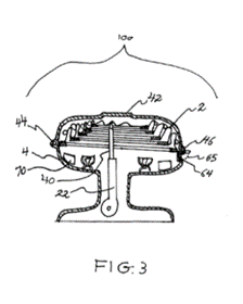
Maszynka do rzucania śnieżkami
Przed świętami pisaliśmy, że możemy nie zobaczyć już śniegu. Jednak ostatnio pogoda nas trochę zaskakuje – maszynka do rzucania śnieżkami sprawdzi się idealnie także po świętach!
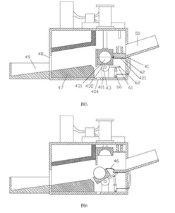
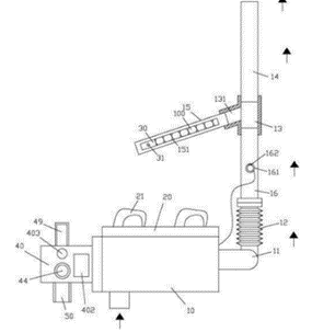
Zastrzeżenie niezależne:
1.An automatic snowball making transmitter comprises a fan (10) and a manufacturing box (40), characterized in that: the fan (10) is fixed on the connecting plate (20), and the connecting plate (20) is fixed with shoulders a manufacturing body (40) is fixed on the outer side wall of the casing of the windshield (21); A bellows (12) is connected to the blowing pipe (11) of the fan (10), and a three-way connecting pipe (13) is connected to the end of the bellows (12), and the front end of the three-way connecting pipe (13) is connected There is a ball tube (14), a side wall tube (131) of the three-way connecting tube (13) is connected with a ball guiding tube (15), and a plurality of balls arranged against each other are placed in the guiding tube (15). (100), the end of the guide tube (15) away from the side wall tube (131) is inserted into the push block (30), and the top surface of the push block (30) is fixed with a push portion (31) and a push portion (31) The insert sleeve has a moving through groove (151) on the top surface of the guide tube (15); The rear side plate of the manufacturing box body (40) has a feeding through hole (41), the feeding trough body (50) is fixed on the rear side plate of the manufacturing box body (40), and the feeding trough body (50) is inclined And disposed in communication with the feed through hole (41), the inner side wall of the rear side plate of the box body (40) is fixed with a horizontal baffle (42), and the horizontal baffle (42) is located at the feed through hole (41). Below, a lower pressing block (43) is hinged to the rear portion of the bottom plate of the making case (40), and a top surface of the top plate of the manufacturing box body (40) is fixed with a pushing cylinder (44) for pushing the cylinder (44) Straight down into the manufacturing box (40) and fixed with the upper pressing block (45), the bottom surface of the upper pressing block (45) is fixed with an upper hemispherical recess (451), and the top surface of the lower pressing block (43) is fixed The lower hemisphere recessed hole (431), the upper pressing block (45) corresponds to the lower pressing block (43), the upper hemispherical recessed hole (451) and the lower hemispherical recessed hole (431) correspond to each other, and one end of the elastic connecting block (46) It is fixed on the front side of the horizontal baffle (42), and the other end is fixed on the rear side of the lower pressing block (43), and the left and right side walls of the upper pressing block (45) and the lower pressing block (43) are closely attached to the manufacturing box. The left and right side walls of the body (40) are fixed with a slant above the front portion of the bottom plate of the box body (40) The block (47), the oblique block (47) is located in front of the lower pressing block (43), and the front end of the diagonal block (47) faces the discharge hole provided on the front side plate of the making case (40) (48). a collecting tank (49) is fixed on the outer wall surface of the front side plate of the making box (40), and the collecting trough (49) corresponds to the discharging hole (48); The top surface of the top plate of the making case (40) is hinged with a push cylinder (60), and the push rod of the push cylinder (60) is hinged to the rotating rod (61) fixed on the lower pressing block (43).
Patent CN105771282 – Automatic snowball making and throwing machine
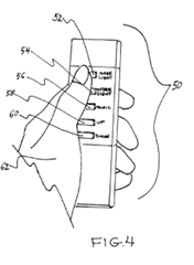
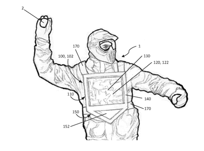
Urządzenie do punktacji i metody punktowania walki na śnieżki
Ten wynalazek powinien znaleźć się w zestawie z maszynką do śnieżek. Przy tak intensywnych opadach jakie zaobserwowano ostatnio w Hiszpanii, można z bitwy na śnieżki uczynić nowy sport narodowy. Patent na stroje i zasady „gry” już mamy.
Zastrzeżenia niezależne:
1. A scoring device to be worn by a person for scoring a snowball fight, the device comprising: a target portion including: a target; a permeable layer coupled to the target in a spaced apart construction to form an interior region between the permeable layer and the target, the permeable layer configured to allow snow from snowballs to pass through the permeable layer and into the interior region; a scoring chamber portion coupled below the target portion, the scoring chamber portion arranged to accumulate and store snow falling from the interior region; and one or more attachment elements configured to attach the device to the torso of the person.
10. A scoring device to be worn by a person for scoring a snowball fight, the device comprising: a target portion including: a target; a scoring chamber portion coupled below the target portion, the scoring chamber portion arranged to accumulate and store snow from snowballs that is falling from the target; a stopper element at least partially separating the target portion from the scoring chamber portion, wherein the stopper element is shaped and arranged to allow snow to enter the scoring chamber portion but limits the amount of snow that exits the scoring chamber portion when the person bends over; and one or more attachment elements configured to attach the device to the torso of the person.
15. A method of scoring a snowball fight: receiving and wearing a scoring device configured to be worn by a person for scoring a snowball fight, the device having: a target portion including: a target; a scoring chamber portion coupled below the target portion, the scoring chamber portion arranged to accumulate and store snow from snowballs that is falling from the target portion, wherein the scoring chamber portion includes a window configured to view snow that accumulates in the scoring chamber portion; a stopper element at least partially separating the target portion from the scoring chamber portion, wherein the stopper element is shaped and arranged to allow snow to enter the scoring chamber portion but limits the amount of snow that exits the scoring chamber portion when the person bends over; one or more attachment elements configured to attach the device to the torso of the person; throwing snowballs at the scoring device such that snow from the snowballs enters the target portion; accumulating snow falling from the target portion in the scoring chamber portion; measuring the amount of snow accumulated in the scoring chamber portion; and
determining a score.
Patent US201615222044 – Scoring device and methods for scoring a snowball fight
Forma na bałwana
Czy lepiąc bałwana byliście zadowoleni z jego kształtów? Nie? To najwyższa pora abyście zapoznali się z tym amerykańskim wynalazkiem, dzięki któremu Wasze dzieło będzie miało idealne, bałwanowe kształty.
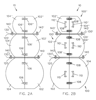
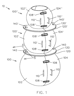
Zastrzeżenie niezależne:
1. A snowman mold, comprising:
a base member defining an interior space and an upper opening in communication with the interior space, and including an annular base flange attached to the base member adjacent to the upper opening, the base flange extending radially outwardly from the base member;
a torso member defining an interior space and a lower opening and an upper opening in communication with the interior space, and including a first annular torso flange attached to the torso member adjacent the lower opening and extending radially outwardly from the torso member, the first torso flange being engaged with the base flange for stacking the torso member on the base member, the torso member further including a second annular torso flange attached to the torso member adjacent the upper torso opening and extending radially outwardly from the torso member;
an aperture defined through the base flange;
an aperture defined through the first torso flange and positioned to register with the base flange aperture;
a fastener adapted to extend through the base flange aperture and through the first torso flange aperture for releasably coupling the torso member to the base member;
wherein the base member includes a first spherical base portion and a second spherical base portion pivotally coupled to the first base portion for movement of the base member between an open and a closed configuration, the first base portion being releasably coupled to the second base portion with a latch for selectably holding the base member in the closed configuration;
wherein the base flange includes a first flange portion attached to the first base portion and a second flange portion attached to the second base portion;
wherein the torso member includes a first spherical torso portion and a second spherical torso portion pivotally coupled to the first torso portion for movement of the torso member between an open and a closed configuration, the first torso portion being releasably coupled to the second torso portion with a latch for holding the torso member in the closed configuration;
wherein the first torso flange includes a first flange portion attached to the first torso portion adjacent the lower torso opening and a second flange portion attached to the second torso portion adjacent the lower torso opening;
wherein the second torso flange includes a first flange portion attached to the first torso portion adjacent the upper torso opening and a second flange portion attached to the second torso portion adjacent the upper torso opening.
Patent US6176464 – Snowman mold
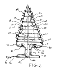
Sztuczna choinka
Co roku ludzie zastanawiają się, czy kupić naturalną czy sztuczną choinkę. Czy rozważający zakup sztucznego drzewka decydują się również na tak abstrakcyjne okazy, jak „choinka” będąca przedmiotem zgłoszenia sprzed ponad 100 lat?
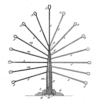
Poniżej także ponad stuletnie zastrzeżenie patentowe:
1. An artificial Christmas tree comprising a plurality of branches each of which is formed from a wire rod bent midway between its ends to form a loop and having its ends 100 twisted together to form the body of the branches, said branches bavin their infier 9 ends twisted together and wound upon each el other to form the trunk of 'the tree, a base having formed therein a central aperture 105 and having in its lower side a recess adapted to receive the lower end of the tree trunk and the radially projecting ends of the branches forming the trunk, and means to secure said ends of the -branches in said 113 recess.
Dostrzegacie jakieś różnice w stosunku do tego, co mamy teraz?
Patent US994248 – Artificial Christmas Tree
Sztuczna choinka (po raz drugi)
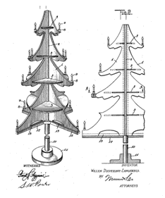
Pozostając w temacie sztucznych drzewek – propozycja drzewka ze świeczkami zamiast bombek. Może warto od razu skorzystać z wcześniej przywołanego systemu gaśniczego choinki świątecznej?
Jedno z zastrzeżeń:
1. An artificial Christmas tree, comprising ornamental wings, a center post, having grooves receiving the inner edges of the wings and shelf located on the post and having removeable interlocking engagement with all of the wings.
Patent US1577207 – Artificial christmas tree
“Sztuczna” choinka (po raz trzeci?)
Kolejny dzień, kolejna choinka. Nie znudziliśmy Was jeszcze tematem choinek? To czas na wyjątkowy wynalazek – elektryczne urządzenie wyświetlające, mające za zadanie… symulowanie choinki!
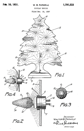
Zastrzeżenie:
A flat member having spaced-apart cylindrical apertures therein, the axes of which are disposed in parallel relation’ – a rubber hushing adapted to be fitted into each aperUre _an annular shoulder at one end of each bus Ing adapted to engage one face of the member, said bushings being frictionall retained in said apertures, and each bu ng having a cylindrical bore adapted to receive and support a device such as an electric light bulb.
Patent US1791533 – Display device
Maszyna do tworzenia pomarszczonych świecidełek
Każdy kto był dzieckiem mógł przygotowywać ozdoby do powieszenia na choinkę. Czasem jednak choinka mogła być tak ogromna, że jedna osoba mogła sobie nie poradzić z produkcją tylu ozdób. W takiej sytuacji pomocny byłby ten wynalazek: maszyna do tworzenia pomarszczonych świecidełek!
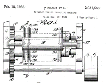
Zastrzeżenie:
A crinkled tinsel producing machine comprising a pair of juxtaposed shafts, a plurality of cutter disks rigidly mounted on said shafts in staggered cooperative relation to each other, a plurality of spacer disks mounted on said shafts intermediate said cutter disks, said spacer disks being of considerably lesser diameter than the diameter of the cutter disks, and floating rings mounted loosely on said shafts whereby the bottom edges of said floating rings extend to and below the lower periphery of said cutter disks.
Patent US2031566 – Crinkled tinsel producing machine
Wynalazca świecących łańcuchów?
Może nam się wydawać, że świecące łańcuchy i lampki na choinkach są od zawsze. Jednak ktoś to musiał kiedyś wymyślić. Jednym z ojców świecących łańcuchów i lampek na choinkach jest z pewnością Curtis Barkes.
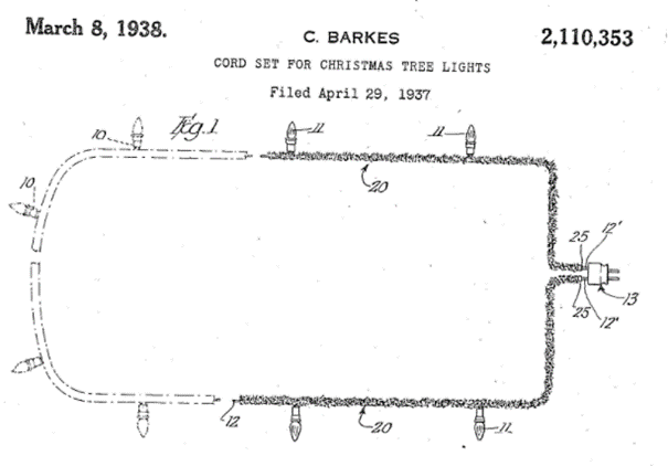
Zastrzeżenie:
A cord set comprising, in combination, a plurality of lamp sockets, a connector, wires electrically associated with said connector and with said sockets to ply energizing current for lighting lamps placed in said sockets, said wires being arranged to provide an elongated string of sockets adapted to be draped about a Christmas tree with.a substantial spacing of the sockets along the string, and a sheath of decorative tinsel fixed about said wires so as to substantially conceal said wires intermediate said sockets.
Patent US2110353 – Cord set for christmas tree lights
Patent na … jemiołę
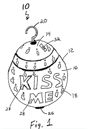
Nawet jemioła jest przedmiotem wynalazku. Tylko to nie jest jemioła (roślina), jaką zna każdy z nas. To ozdoba, która świeci i odtwarza piosenkę, gdy wykryje pod sobą ruch. Mamy nadzieję, że wykrytym ruchem będzie, rzecz jasna, pocałunek!
Jak wskazuje zastrzeżenie niezależne:
1. A hanging mistletoe ornament, comprising:
a shell;
a control unit mounted in said shell, wherein said control unit is preprogrammed to include a predetermined sound stored in memory;
a speaker connected to said shell and said control unit for playing said sound; and
a motion sensor connected to said outer shell and said control unit for generating a signal that is sent to said control unit if motion is detected by said motion sensor, wherein said control unit plays said sound in response to said signal from said motion sensor.
Patent US2002126506 – Hanging mistlettoe ornament
Renifery podłączone do silnika elektrycznego
Zapracowane renifery wożą Św. Mikołaja po całym świecie, aby ten mógł rozdać prezenty grzecznym dzieciom. Jeden z ostatnich patentów na naszej liście dotyczy właśnie reniferów – ale nie byle jakich! Nie trzeba się obawiać o ich zmęczenie, bo Św. Mikołaj znalazł na to sposób – renifery podłączone do silnika elektrycznego!
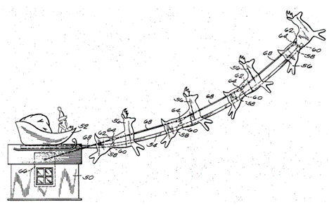
Zastrzeżenie niezależne:
1. An animated display comprising support means including an elongated arm, a first figure attached to said support means, said first figure being shaped to represent a vehicle, a plurality of animal figures each pivotally attached to said arm, said animal figures being spaced in a line along said arm, each of said animal figures being shaped to represent a draft animal, linkage means interconnecting said animal figures together, and means for actuating said linkage means and thereby simultaneously rocking the entire line of animal figures about their pivotal attachment to the arm to simulate a galloping motion of said animal figures, said animal figures being pivotally attached to said arm in pairs abreast by means of U-shaped brackets which pass through openings in said arm, the upper ends of each U-shaped bracket being bent over to form support arms for a pair of said animal figures, there being a pair of animal figures attached to each pair of said bent over support arms, and the openings in said arm for said U-shaped brackets being spaced along said arm to form a line of said pairs of animal figures.
Patent US3820265 – ANIMATED DISPLAY
Ozdoba choinkowa
W wigilię zaprezentowaliśmy Państwu wyjątkowy wynalazek – ozdobę choinkową. Być może mogłaby pomóc w świątecznych przygotowaniach? Rąk do pracy nigdy zbyt wiele.
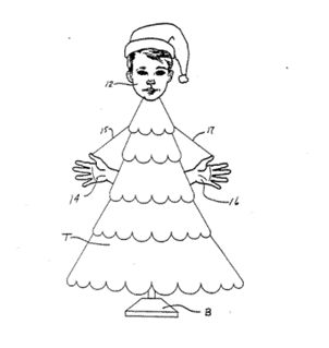
Zgodnie z zastrzeżeniem:
1. Christmas tree ornaments for decorating a tree in a manner simulating a human individual, comprising: a first elongated adjustable strut having a plurality of relatively slidable telescoping sections; a first ornament member secured adjacent one end portion of said strut; said first ornament member including a first electrical light and a representation of a human head; a second elongated adjustable strut having a plurality of relatively slidable telescoping sections; a second ornament member secured adjacent one end portion of said second strut; said second ornament member including a second electrical light and a representation of a human hand; a third elongated adjustable strut having a plurality of relatively slidable telescoping sections; a third ornament member secured adjacent one end portion of said third strut; said third ornament member including a third electrical light and a representation of a human hand; power cord means extending through each of said struts and connected to each of said electrical lights; and a plurality of arcuate clamps on each of said struts for securing said struts to a Christmas tree, each of said clamps having a pair of spring biased jaws.
Patent US4939004 – Christmas tree ornament